Abstract
Providing an accurate soft-tissue transfer for anterior implants is not a new concept; however, it is currently an especially relevant one. There are numerous documented cases in which residual excess cement with cement-retained implant restorations was a contributing cause in peri-implantitis. In 2012, Wadhwani et al reported the importance of placing the crown abutment margins supragingivally for ease of cement removal as a possible solution to address this important issue. Therefore, if placement of the crown abutment margin location is imperative, making an impression that reproduces the soft tissue is equally critical. In 1997, this author introduced the “custom impression coping” to achieve such an accurate transfer. Given the wide use of intraoral digital impressions in 2014, this discussion describes how to fabricate a “custom scan body” using that technology to replicate the transition zone in the virtual environment.
Compared to its early years, implant dentistry has progressed significantly, with new implant designs, new surfaces, narrow diameters, bone level fixtures, and new lengths—short and long. However, implant manufacturers continue to fabricate round components (impression copings) to transfer anatomical shapes for laboratory fabrication of the definitive prosthesis. It is specifically because anterior teeth are not round that they require methods to accurately transfer the custom shape formed by a provisional restoration. There have been several attempts to improve the transition zone with changes at the table of the fixture. In 2003, Wörhle1 invented a scalloped implant (Nobel Perfect™ Esthetic Scalloped Implant, Nobel Biocare®, www.nobelbiocare.com) for the purpose of preserving or establishing interdental bony peaks that support the soft tissue, thereby maintaining or creating inter-implant papillae. However, clinicians still depend on transitioning from a round, flat implant table to an anatomical form using a custom-shaped abutment.
Yet, although implant dentistry has progressed, clinicians are starting to observe peri-implantitis. There are numerous documented cases in which residual excess cement in cement-retained implant restorations was determined to be a contributing cause of peri-implantitis.2-5 The American Academy of Periodontology sponsored a white-paper consensus conference in April 2013 to address this important issue and reported excess cement as the third risk factor. In 2012, Wadhwani et al6,7 recommended that the crown abutment margin be placed supragingivally for ease of cement removal. In addition, to avoid an unesthetic transition due to gingival recession, he suggested fabricating the supporting abutment in the same shade as the prosthesis (crown). With the use of a zirconia abutment, the ceramist could use either pressed ceramics or layered porcelain. Another option presented is using a custom abutment with a 3600 ceramic collar, which was introduced in 1997 by Marchack and Yamashita.8
As placement of the crown abutment margin location is significant, making an impression that accurately reproduces the peri-implant tissue is equally critical. In 1997, the author introduced the “custom impression coping” to make this accurate transfer.9 He described a technique to use the provisional to duplicate the tissue portion and then replicate the anatomical shape by modifying the open-tray impression coping for an accurate transfer. Given the wide use of intraoral digital impressions at this time, this discussion describes a technique using that technology to fabricate a custom scan body that accurately replicates the transition zone in the virtual environment.
Clinical Presentation
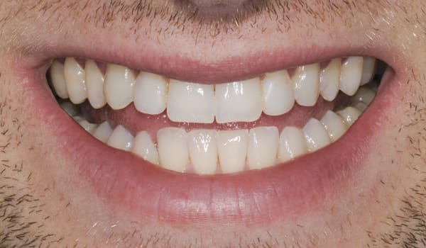
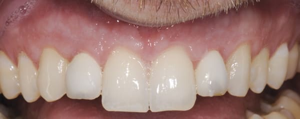
A 25-year-old male patient first presented in August 2000 with congenitally missing maxillary lateral incisors. Both right and left deciduous lateral incisors were present, with a middle-to-low smileline, Class I occlusion, and post-orthodontic treatment. At initial presentation, the recommendation was to maintain the deciduous dentition until completion of the patient’s growth, which was estimated to be 20+ years of age.10 Fortunately, the deciduous teeth were retained, which aided in the development of the alveolar ridge and provided normal periodontium and level gingival tissue, as shown in Figure 1 and Figure 2. The mesial-distal clinical and surgical space was 6 mm on both implant sites between the adjacent teeth (Figure 3 and Figure 4). The patient was treatment planned for immediate placement of 3.3-mm bone level implants and immediate provisionalization to maintain the peri-implant papillae and surrounding tissues.11-16
The presurgical preparation17 performed included surgical guide fabrication as well as an indirect, one-piece, screw-retained provisional restoration with 3.3-mm temporary cylinders and an Essex retainer to be used if immediate provisionalization was not possible.
Implant surgery was initiated by a full-thickness flap on the facial aspect of the anterior teeth, from the upper right second premolar to the upper left second premolar. Primary teeth were extracted and 3.3-mm x 10-mm bone-level implants were placed in sites Nos. 7 and 10 using a surgical guide.17 Implant Stability Quotient (ISQ) readings were 62 and 64. Immediate provisionals were placed with minor modification of interproximal contacts and occlusal adjustments to avoid any contact with the opposing dentition. Both implant sites Nos. 7 and 10 were grafted on the mid-facial with mineralized freeze-dried bone allograft (FDBA) and long-term collagen membrane.
Four months postoperatively, it was observed the provisional restorations provided an excellent soft-tissue response, stable interproximal papillae, and evidence of maintaining the same gingival height (Figure 5 through Figure 7).
Custom Scan Body Technique
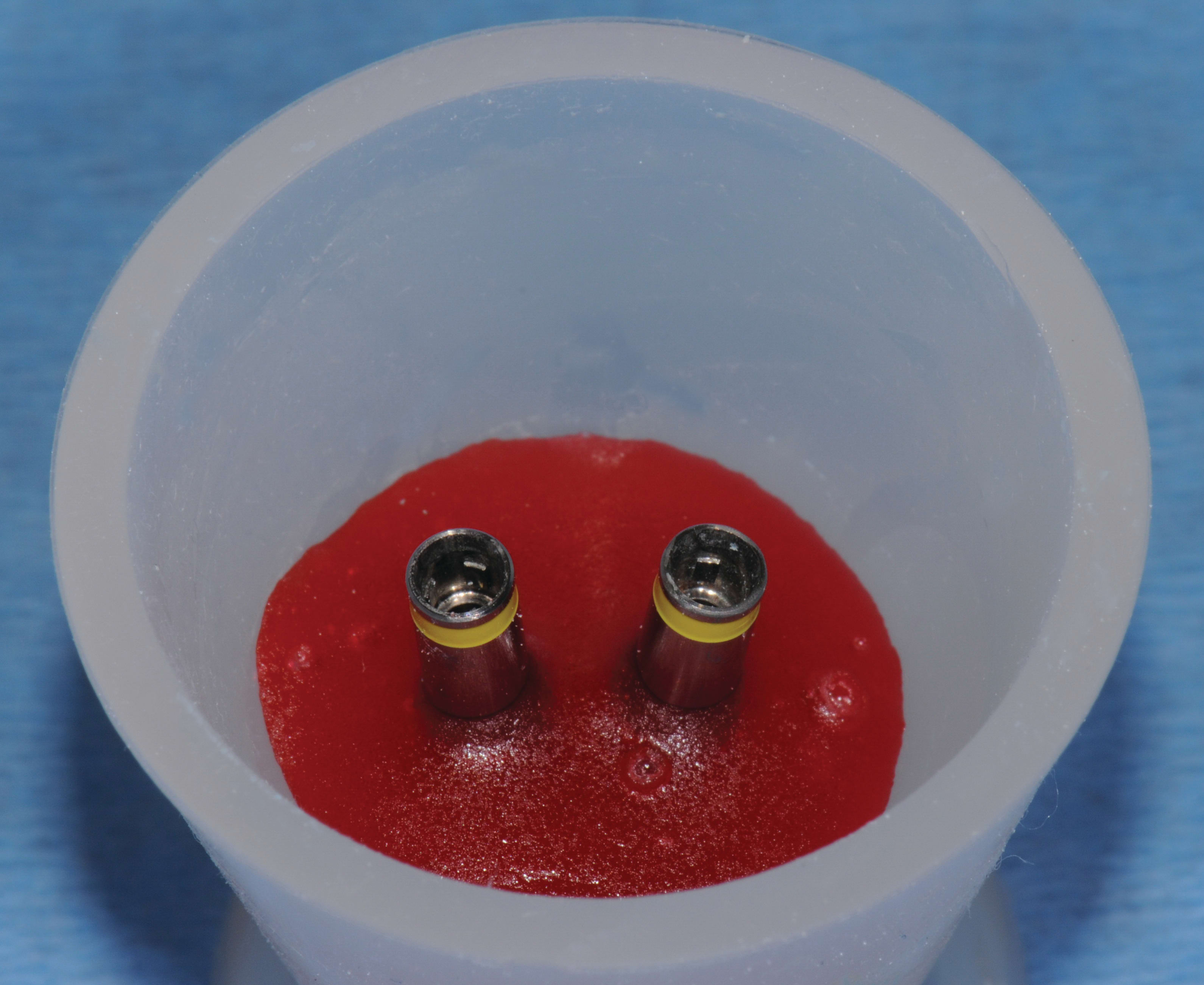
Step 1—Prior to the restorative appointment, two 3.3-mm bone-level implant replicas were placed into a small flexible mixing cup with pattern resin, as shown in Figure 8.
Step 2—The patient’s one-piece provisionals were removed, and cotton was placed in the implant sites to avoid collapse of the peri-implant tissue while using the provisionals for the transfer technique (Figure 9).
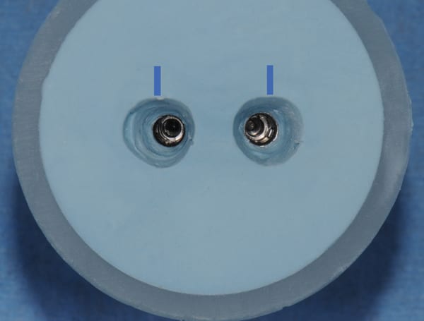
Step 3—Both provisionals were attached to the replicas, and VPS bite registration material was injected to fill the cup, then contoured around all surfaces; a line marked on the facial was used to maintain orientation (Figure 10 and Figure 11).
Step 4—The provisionals were removed from the replicas and reattached to the patient’s implants. Note the replication of the soft-tissue portion of the provisional generated in Figure 12.
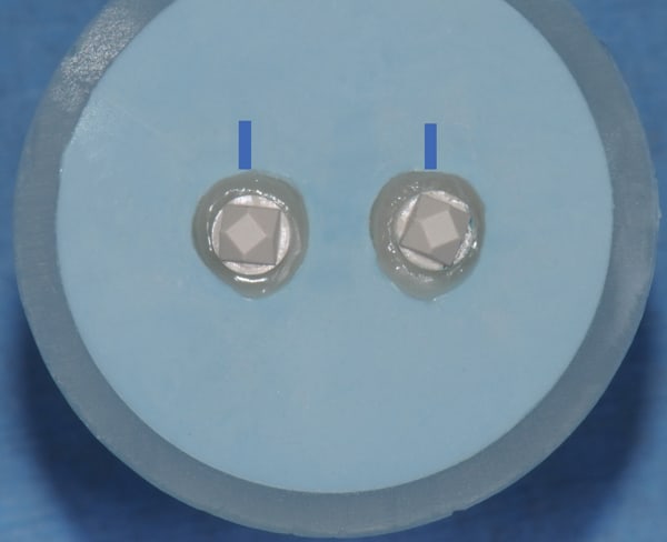
Step 5—The 3.3-mm two-piece scan bodies were attached to the replicas. Note the difference of the form created, as compared to the stock round components in Figure 13.
Step 6—Composite resin was injected/compressed around the scan bodies and light-cured to mimic the soft-tissue portion of the provisionals. The scan bodies were removed, then surface voids were filled with composite resin and smoothed with a white rubber porcelain polishing wheel (Figure 14).
Step 7—Figure 15 shows a comparison between the stock round shape and the “custom scan body” generated. Although, the soft tissue form has been replicated, the gingival margin has not been identified yet.
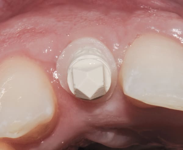
Step 8—The provisionals were removed from the patient’s implants and the custom scan bodies were attached. Finally, the composite resin collar was prepared to the gingival tissue level with a flat-nose high-speed diamond (Figure 16). The scan body will provide the laboratory with a prescribed soft-tissue level in the digital impression (Figure 15, right image). This is the most critical step.
Digital Workflow with Anterior Implants
The digital workflow proceeds as follows: custom scan body to intraoral digital impression to STL file to virtual design program to CAD/CAM abutments to master cast with abutment to definitive prosthesis.
There are currently numerous intraoral digital impression systems on the market and the numbers are growing rapidly. Implants require a scan body (digital impression coping) that will be scanned by an intraoral digital impression system to create a stereolithography (STL) file. Scan bodies are manufactured in one or two pieces; however, most clinicians prefer the one-piece design. The STL file is then downloaded into a design program. In addition, STL files provide the option to produce an actual working cast (master cast). Master casts are either created by computer-aided design/computer-aided manufacturing (CAD/CAM) modeling of urethane material (itero, Align Technology Inc., www.itero.com) or 3D printing. Digitally generated casts are considered as accurate as traditional diestone18; Ender et al19 reported a trueness value of +/- 35 micron on a full-arch scan. Following the design of the abutments in the virtual environment, the virtual abutments are sent to a milling center for CAD/CAM manufacturing. Most laboratories still require a master cast to connect the actual abutments for the fabrication of the definitive cementable prosthesis.
Restorative
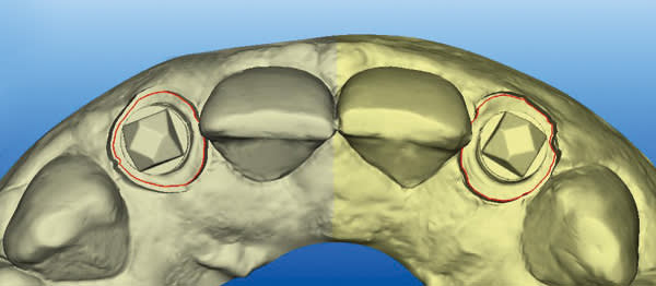
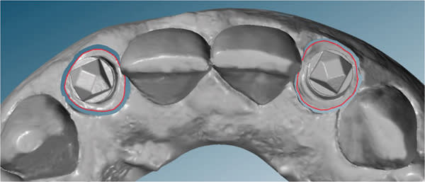
An intraoral digital impression of both custom scan bodies No. 7 and No. 10 was made with the itero digital impression system to create an STL file (Figure 17 and Figure 18). The custom shape of the scan bodies is clearly seen with red line margins in both the facial and occlusal views shown in Figure 19 and Figure 20.
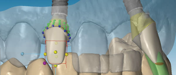
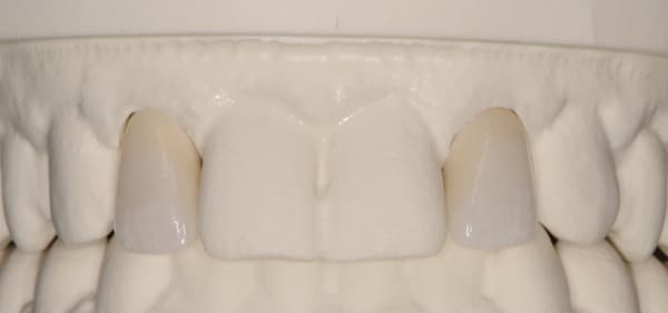
The STL files were downloaded into the design program, creating a virtual working cast. The virtual cast illustrates the red margin line created by the custom scan body transfer, which will guide the laboratory in the designing of the definitive abutment margins (Figure 21). In addition, the STL files were utilized to fabricate a master cast created by CAD/CAM modeling of urethane material. The completed abutment design shows a dotted blue line depicting the margin line created from the custom scan body transfer (Figure 22). The virtual abutments’ STL files were then uploaded to the design software for CAD/CAM fabrication of the definitive zirconia abutments. After the abutments were received back at the laboratory, they were placed on the master cast, evaluated/modified (Figure 23), and scanned into prosthesis design software. The definitive prostheses were fabricated with zirconia copings and layered porcelain.
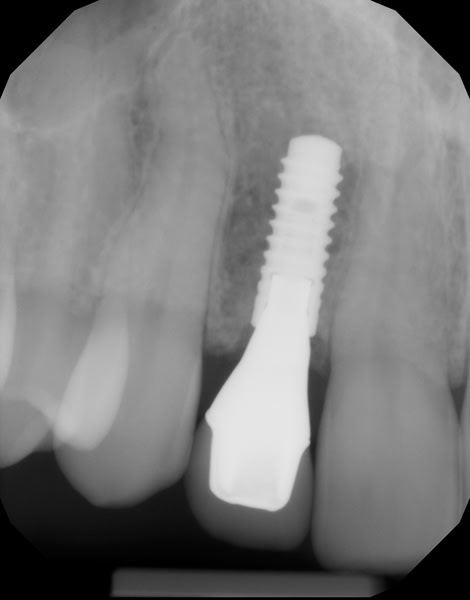
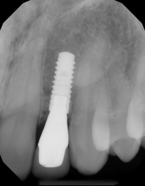
Both provisional restorations were removed, the definitive abutments were connected, and the abutment screws were torqued to 35 Ncm. The accuracy of the abutment margins at the gingival level, as transferred from the original custom scan body, is demonstrated in Figure 24. A cotton pellet and elastic, single-component, light-cured resin was placed to close the abutment access hole and light cured. The definitive restorations were cemented with radiopaque glass ionomer luting cement (Figure 25 through Figure 29).
Discussion
The “custom impression coping” was introduced in 1997 and proved to be a valuable tool to aid in the transfer of anatomical healed anterior soft tissue to the laboratory for the fabrication of the definitive implant prosthesis. However, the actual “custom impression coping” did not include the exact tissue level, just the anatomical form. The traditional open-tray implant impression is poured in diestone with soft-tissue moulage. The laboratory is provided with a master cast with clearly defined gingival tissue margins. Thus, with the traditional technique, it is not necessary to provide the tissue level in the actual “custom impression coping.”
However, when utilizing intraoral digital impressions, laboratory technicians are designing CAD/CAM abutments in a virtual environment without hard parameters. If the margins of the custom scan body are contoured to the gingival tissue level, the technician will have clearly defined margins to target in the design process. The result will be a more accurate, more consistent definitive prosthesis and improved esthetic outcome.
Conclusion
The main advantages of using a “custom scan body” with anterior intraoral digital impressions include that it provides the following: a diagnosed tissue level and anatomical form of the peri-implant tissue in the virtual environment; a more accurate soft-tissue transfer for abutment fabrication in the virtual environment; a more accurate crown abutment margin at the tissue level for the ease of cement removal and avoiding complications such as peri-implantitis; and an improved communication with the dental laboratory for ease of delivery of the definitive prosthesis.
Indications include all anteriors and implants placed in non-ideal locations where an accurate soft-tissue transfer is beneficial.
This introduction to an improvement in the digital transfer of anterior implants represents a first step. The next step would be a technological advancement to provide a digital scan (STL file) of the custom scan body independently and merge the STL files together with the virtual working cast. Together, these data provide the technician with the internal soft-tissue form as well as the implant position and gingival tissue level.
ABOUT THE AUTHOR
Kenneth F. Hinds, DDS
Past President, Academy of Osseointegration;
Private Practice, Laguna Niguel, California
References
1. Wöhrle PS. Nobel Perfect esthetic scalloped implant: rationale for a new design. Clin Implant Dent Relat Res. 2003;5 Suppl 1:64-73.
2. Raval NC, Wadhmani CP, Jain S, Darveau RP. The Interaction of Implant Luting Cements and Oral Bacteria Linked to Peri-Implant Disease: An In Vitro Analysis of Planktonic and Biofilm Growth - A Preliminary Study. Clin Implant Dent Relat Res. 2014 Jun 6, doi: 10.1111/cid.12235 [Epub ahead of print]
3. Wadhwani C, Rapoport D, La Rosa S, et al. Radiographic detection and characteristic patterns of residual excess cement associated with cement-retained implant restorations: a clinical report. J Prosthet Dent. 2012;107(3):151-157.
4. Wilson TG Jr. The positive relationship between excess cement and peri-implant disease: a prospective clinical endoscopic study. J Periodontol. 2009;80(9):1388–1392.
5. Pauletto N, Lahiffe BJ, Walton JN. Complications associated with excess cement around crowns on osseointegrated implants: a clinical report. Int J Oral Maxillofac Implants. 1999;14(6):865–868.
6. Wadhwani C, Pineyro A, Akimoto K. An introduction to the implant crown with an esthetic adhesive margin (ICEAM). J Esthet Restor Dent. 2012;24(4):246–254.
7. Linkevicius T, Vindasiute E, Puisys A, Peciuliene V. The influence of margin location on the amount of undetected cement excess after delivery of cement-retained implant restorations. Clin Oral Implants Res. 2011;22(12):1379-1384.
8. Marchack CB, Yamashita T, A procedure for a modified cylindric titanium abutment. J Prosthet Dent. 1997;77(5):546-549.
9. Hinds K. Custom impression coping for an exact registration of the healed tissue in the esthetic implant restoration. Int J Periodontics Restorative Dent. 1997;17(6):584-591.
10. Kinzer GA, Kokich VO Jr. Managing congenitally missing lateral incisors. Part III: Single-tooth implants. J Esthet Restor Dent. 2005;17(40):202-210.
11. Kan JY, Rungcharassaeng K, Lozada JL, Zimmerman G. Facial gingival tissue stability following immediate placement and provisionalization of maxillary anterior single implants: a 2- to 8-year follow-up. Int J Oral Maxillofac Implants. 2011;26(1):179-187.
12. Oyama K, Kan, JY, Rungcharassaeng K, Lozada J. Immediate provisionalization of 3.0-mm-diameter implants replacing single missing maxillary and mandibular incisors: 1-year prospective study. Int J Oral Maxillofac Implants. 2012;27(1):173-180.
13. Robertsson S, Mohlin B, Thilander B. Aesthetic evaluation in subjects treated due to congenitally missing maxillary laterals. A comparison of perception in patients, parents and dentists. Swed Dent J. 2010;34(4):177-186.
14. Elian N, Bloom M, Dard M, et al. Radiological and micro-computed tomography analysis of the bone at dental implants inserted 2, 3 and 4 mm apart in a minipig model with platform switching incorporated. 2014;25(2):e22-e29.
15. Chow YC, Wang HL. Factors and techniques influencing peri-implant papillae. Implant Dent. 2010;19(3):208-219.
16. Nisapakultorn K, Suphanantachat S, Silkosessak O, Rattanamongkolgul S. Factors affecting soft tissue level around anterior maxillary single-tooth implants. Clin Oral Implants Res. 2010;21(6):662-670.
17. Clem D, Hinds K. The Team Approach to Replacing the Congenitally Missing Lateral Incisor: Restorative and Periodontal Considerations. Clinical Advances in Periodontics. 2013;3(2).
18. Lee SJ, Betensky RA, Gianneschi GE, Gallucci GO. Accuracy of digital versus conventional implant impressions. Clin Oral Implants Res. 2014 Apr 10. doi: 10.1111/clr.12375. [Epub ahead of print]
19. Ender A, Mehl A. Influence of scanning strategies on the accuracy of digital intraoral scanning systems. Int J Comput Dent. 2013;16(1):11-21.
